
Lesson 6 of 6
Building the VCA
Put everything together and build a Vactrol-based VCA.
Okay. Now we have all the tools to build the VCA. Check out the following diagram and inspect it. You will find familiar sections.
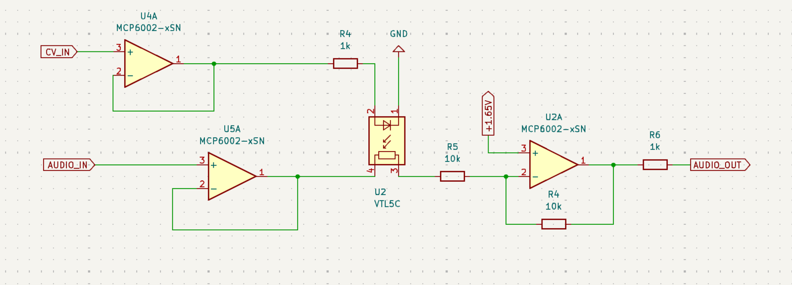
Let me walk you through it:
- Both the U4A and U5A opamps are buffers for the input voltages.
- The Vactrol's LED side is wired the same way as in the previous lesson.
- U2A is wired as an inverting amplifier.
- Without the Vactrol, this opamp has unity gain (R4/R5).
- But with the Vactrol, the gain looks like this:
R4 / (R5 + Vactrol)- The Vactrol's resistance is about 10M ohms when there's no current through the LED side.
- So, if CV_IN is 0V, the gain is almost 0.
- As CV_IN increases, the Vactrol's resistance goes down, so the gain goes up to unity.
- That's literally a VCA.
- The R6 resistor sets the output impedance to 1k.
🎉 Yeah! Now you understand the complete VCA circuit, as we promised in the beginning.
Once you build it, you should see something like this on the oscilloscope:
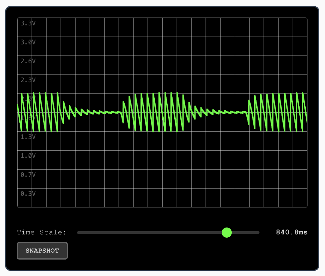
Try the following experiments:
- Feed the 16bit's A2 output, which gives a super-saw waveform.
- Feed some external audio via the line in.
- Use the envelope generator as the CV.