
Lesson 2 of 6
Voltage Dividers
Learn about resistors, voltage dividers, impedance, the loading effect and the 10X rule.
Here we will talk about voltage dividers and the 10X approximation rule.
0. Resistance & Ohm Values
A resistor is a component used to restrict the flow of current. We call this resistance.
- We measure it in ohms (Ω).
- The higher the ohm value, the higher the resistance.
- The higher the ohm value, the lower the current passing through the wire.
- If you connect 3.3V directly to 0V (ground), it will short the setup and may kill parts of the lab kit. But if you use a resistor (1k or higher) in between, it will be fine.
- The resistor does some work (as heat) and holds the entire 3.3V across it.
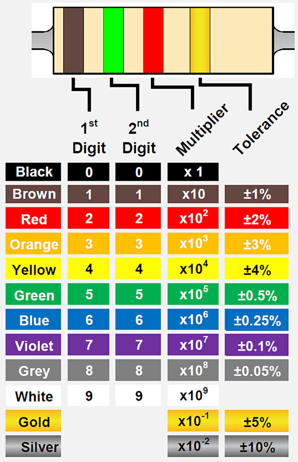
- Resistors use a color code & here's how you can read the value.
(We have labeled the resistors in the component kit, so you can skip this for now.)
1. Voltage Divider Theory
Using resistors, we can divide a given voltage into fractions of it. Here's what a typical voltage divider looks like:
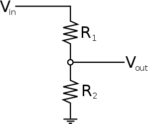
- In our case, Vin is our 3.3V.
- The bottom-most symbol is the ground and it's 0V in this case.
- Vout is the divided voltage.
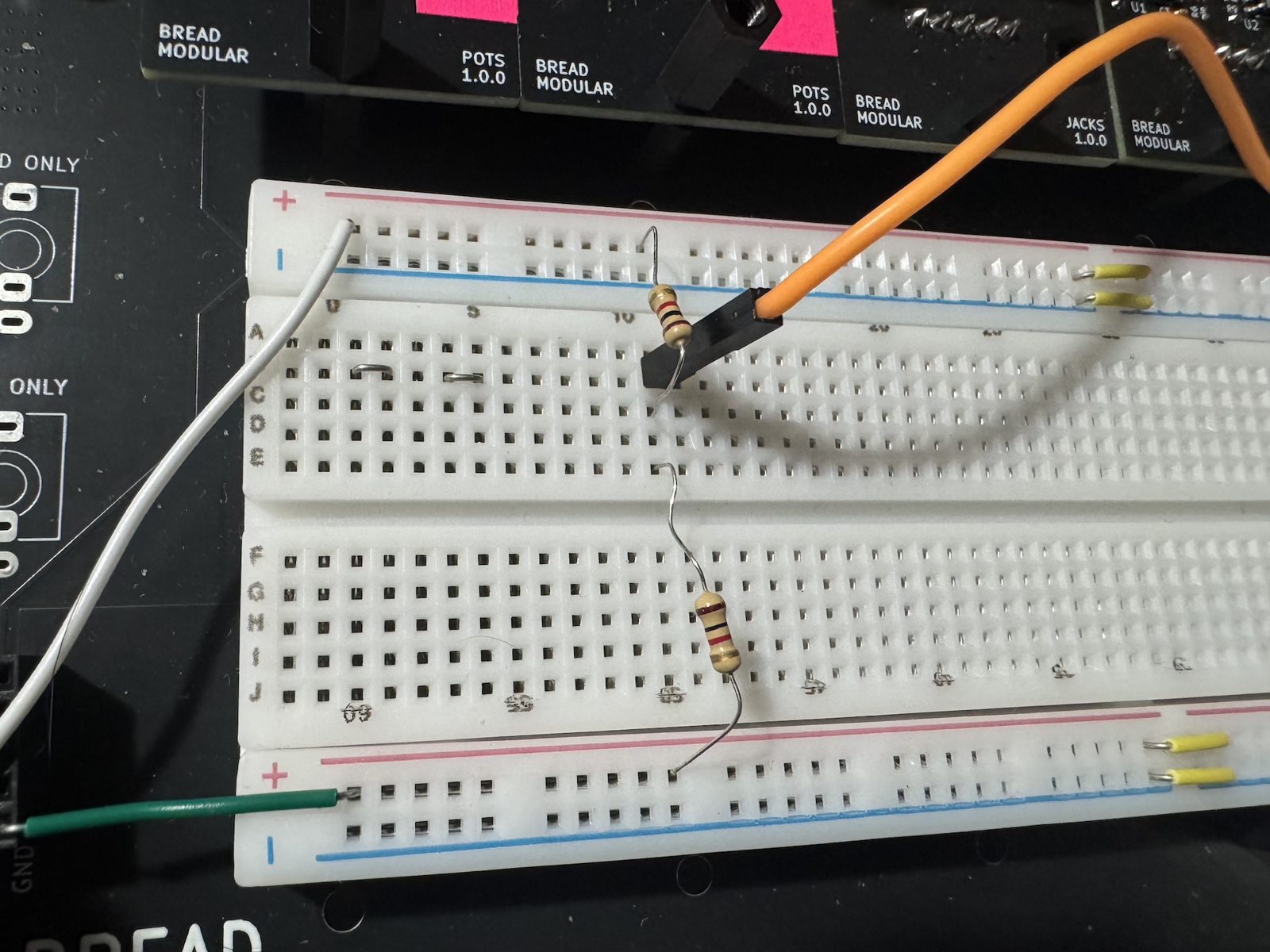
Now use 1k resistors (for both R1 and R2) to make a simple voltage divider, and inspect the voltage at Vout with the oscilloscope.
💡 Here's a rule of thumb for calculating Vout:
- If both R1 and R2 are the same, Vout is 1/2 of Vin.
- If R2 is 10X larger than R1, almost all of the voltage is across R2 (which is Vout).
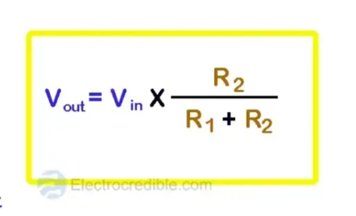
- Otherwise, use the following calculation:
2. Cascading Dividers
If you divide 3.3V in half using 1k resistors, you get 1.65V as Vout. Now, using another pair of 1k resistors, try to divide that Vout in half.
(In this case, the new Vin is the Vout of the first divider.)
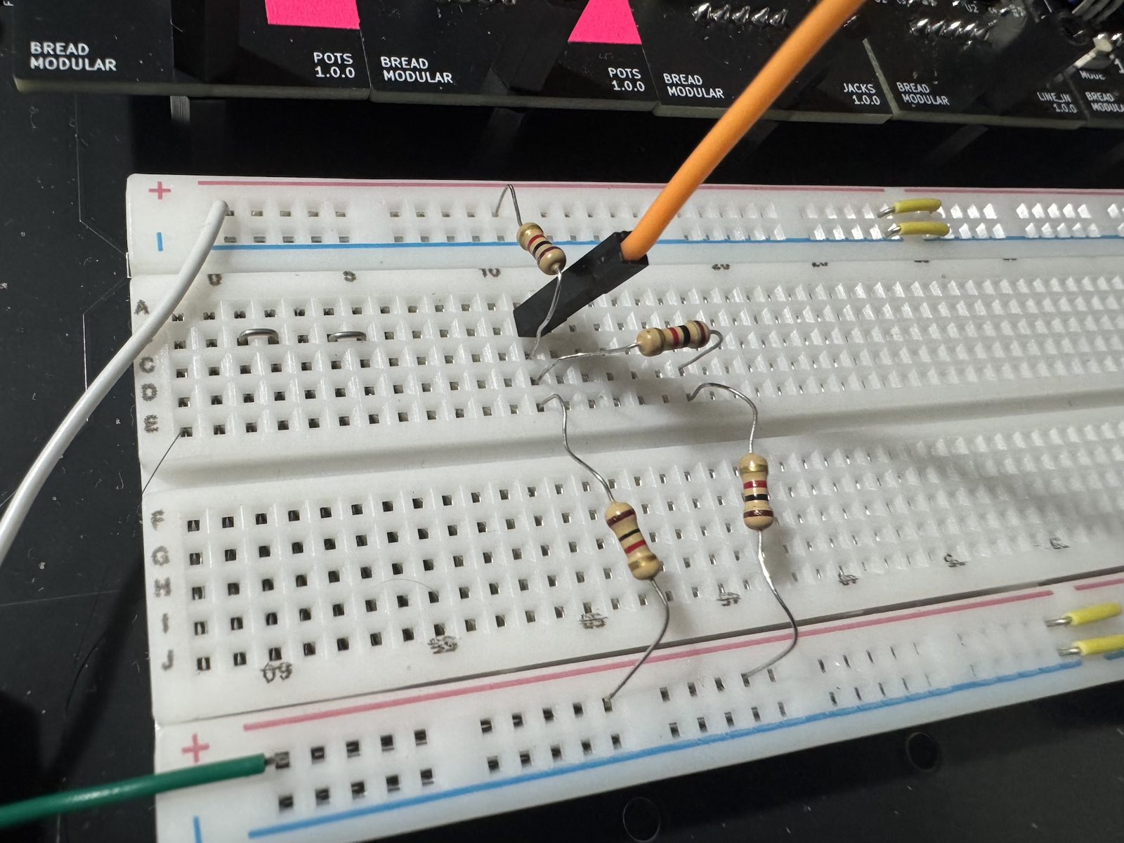
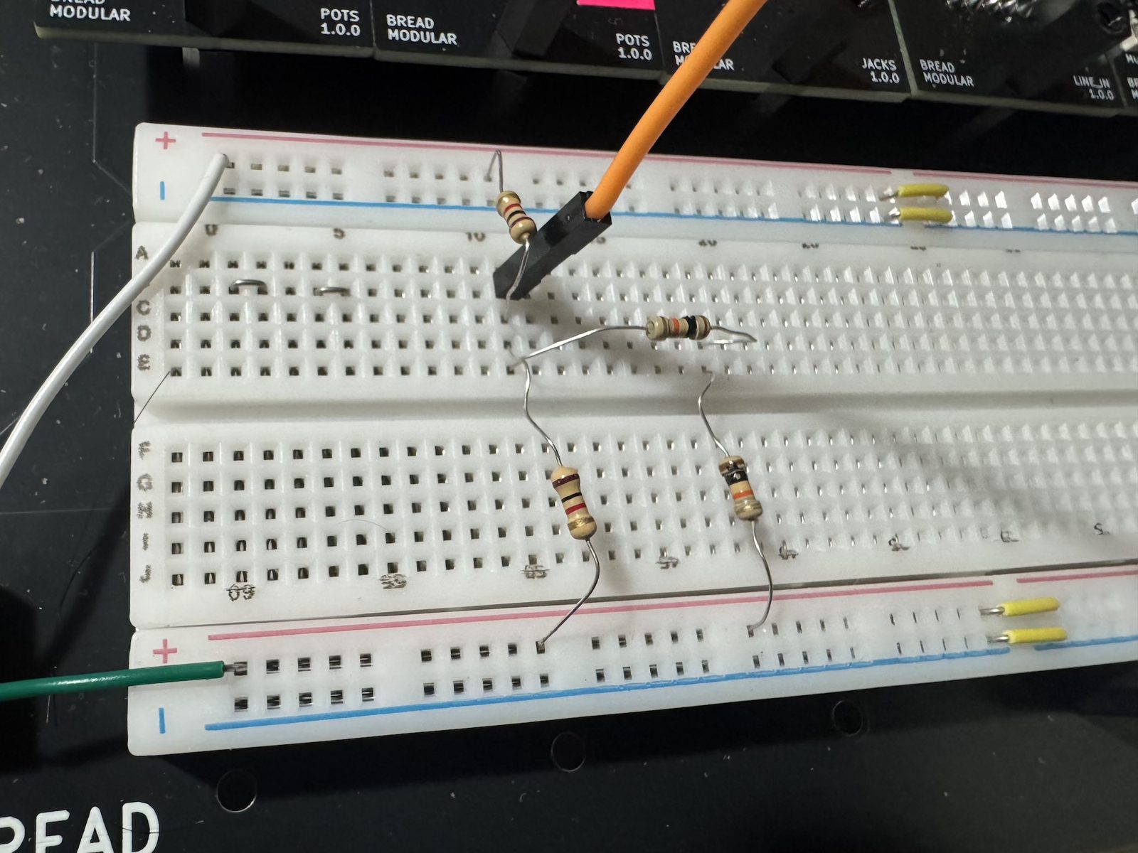
Now, instead of 1k, use 10k resistors for the second divider.
3. Loading, Impedance & the 10X Rule
The voltage drop you have just seen is known as the loading effect. To understand it, we need to learn about impedance.
Impedance
Don't worry too much about what it actually means. Every electronic circuit has an impedance value. For a voltage divider, it's like this:
- If R1 and R2 are the same, the impedance (Zout) is R1/2.
(In our case, since both resistors are 1k, it's 0.5k ohms.) - If R1 is 10X smaller than R2, the impedance is close to R1.
- Otherwise, it's always smaller than the smallest resistor.
Loading Effect
Let's have a look at the loading effect:
- Our main divider has 0.5k impedance.
- Our second 1k divider also has 0.5k impedance, and there's a significant voltage drop.
- Our second 10k divider has 5k impedance, and the voltage drop is minimal.
💡 The Impedance 10X Rule
- If the loading circuit's (our second divider's) impedance is 10X higher than the output impedance, the voltage drop is around 10%.
- If the loading impedance is 100X higher, the voltage drop is around 1%.
In electronics, the 10X rule helps us connect multiple circuits together without worrying about voltage drops or doing large calculations to find them.
In Bread Modular:
- Every output pin's impedance is 1k ohms.
- Every input pin's impedance is higher than 10k ohms.
Because of that, you can mix and match different modules without worrying about volume drops or unexpected results.
4. Feeding Audio to a Voltage Divider
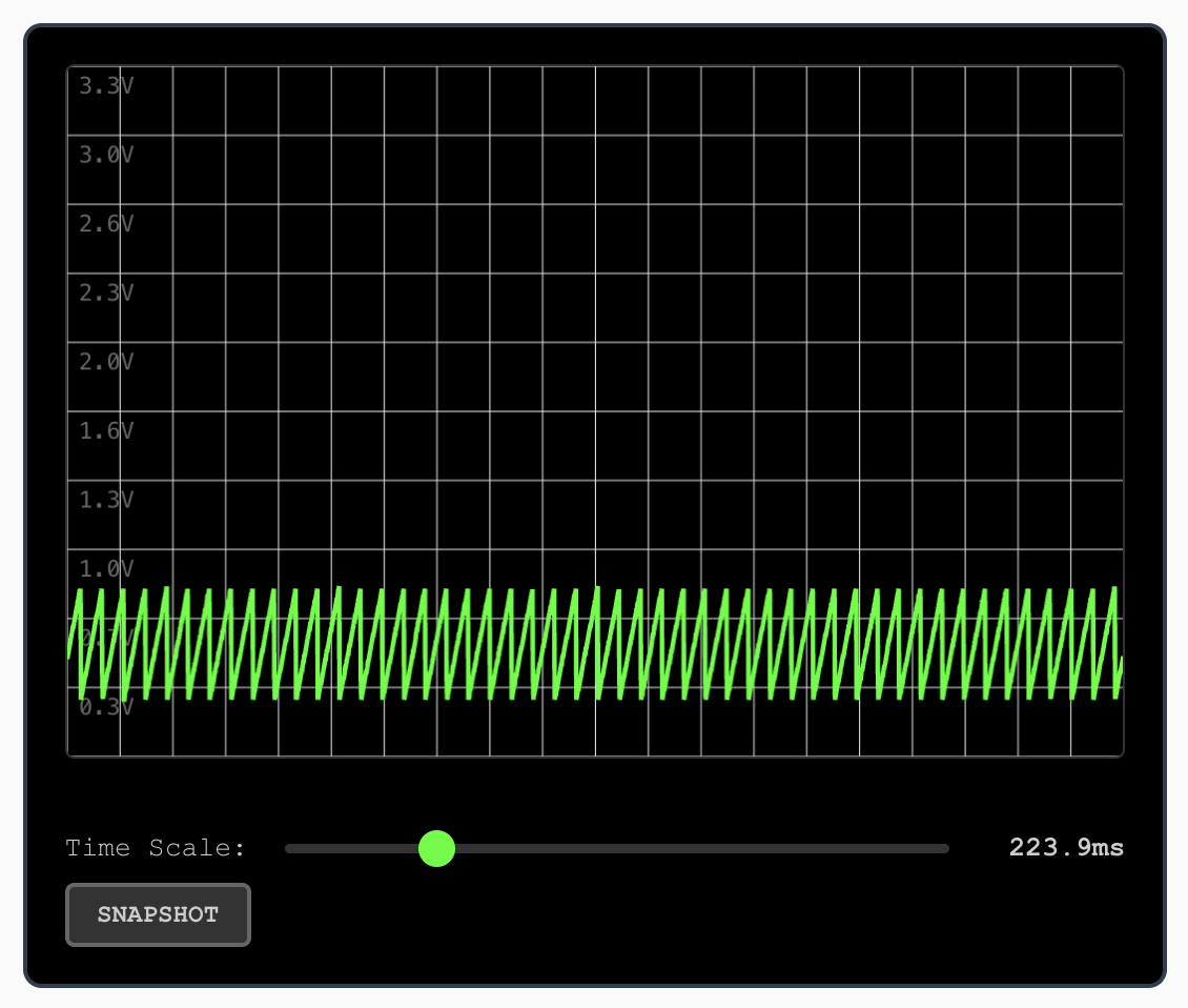
Instead of sending 3.3V to the divider's input, feed it some audio. You can use the 16bit's A1 output (or pick any audio output in the kit).
Use a 1k divider.
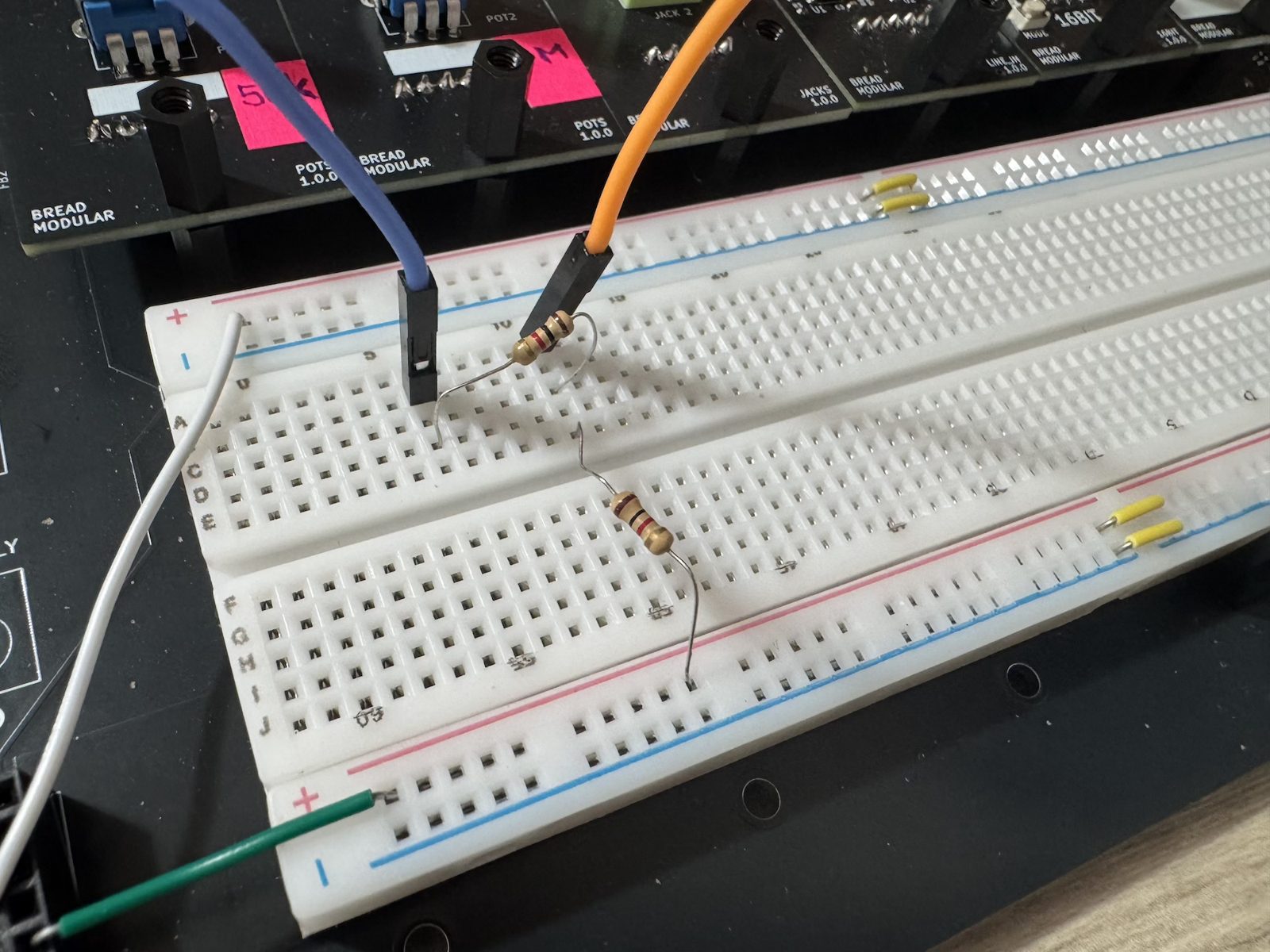
The result will look like this:
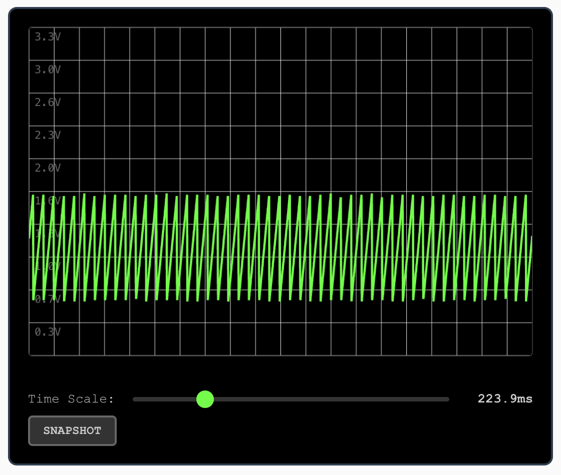
Now use a 10k divider.
This should be the result:
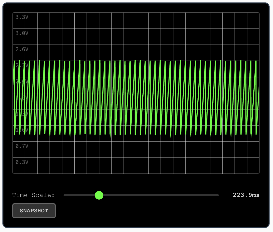
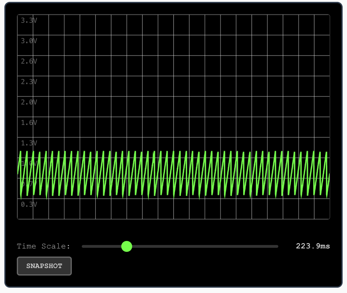
💡 Can you see the difference? This is the loading effect in practice. Our output impedance is 1k. A 1k divider has 0.5k impedance, so it loads the source and affects the result.
But when we use 10k resistors (it's not quite the 10X rule, since the impedance is 5k), the waveform looks as it should.
🚨 The 16bit A1's input impedance is 100k. We currently use it as an oscilloscope probe, but it's not designed for that purpose. So, when you measure a voltage with an impedance beyond 50k, you will notice issues in the measurements (as the 16bit A1 loads the circuit).
You can test this by measuring a divider made with 1M resistors. It shows incorrect results.
We will show you a trick in the next lesson to bypass this limitation.
5. Using a Potentiometer as a Voltage Divider
A potentiometer has three pins. It's basically a voltage divider, but you can change the resistor values as you turn the knob.
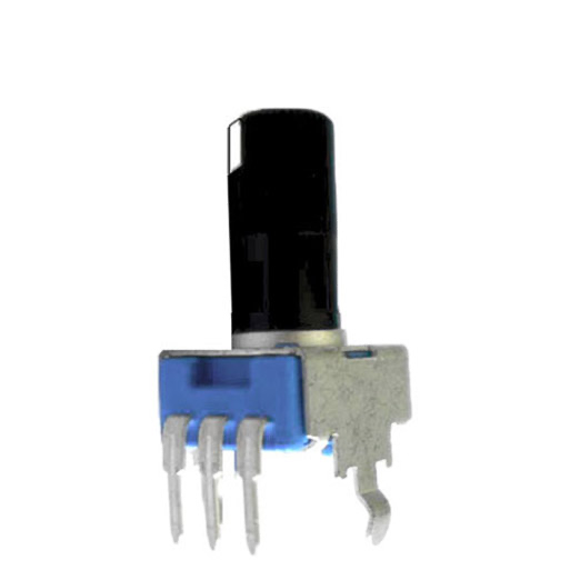
If we name these pins 1, 2 and 3, then:
- 1 - Voltage input
- 2 - Vout
- 3 - Ground
🚨 Do not send 3.3V directly into the potentiometer. At one end of the knob, the resistance will be close to 0 ohms and it will short the circuit.
Make sure to use at least a 1k resistor in series.
The 16bit A1 output has 1k impedance, which acts like a 1k resistor in series. So, you can feed it in as the voltage input.
Now use the 50k pots module and feed it the 16bit A1 output. Then turn the knob.
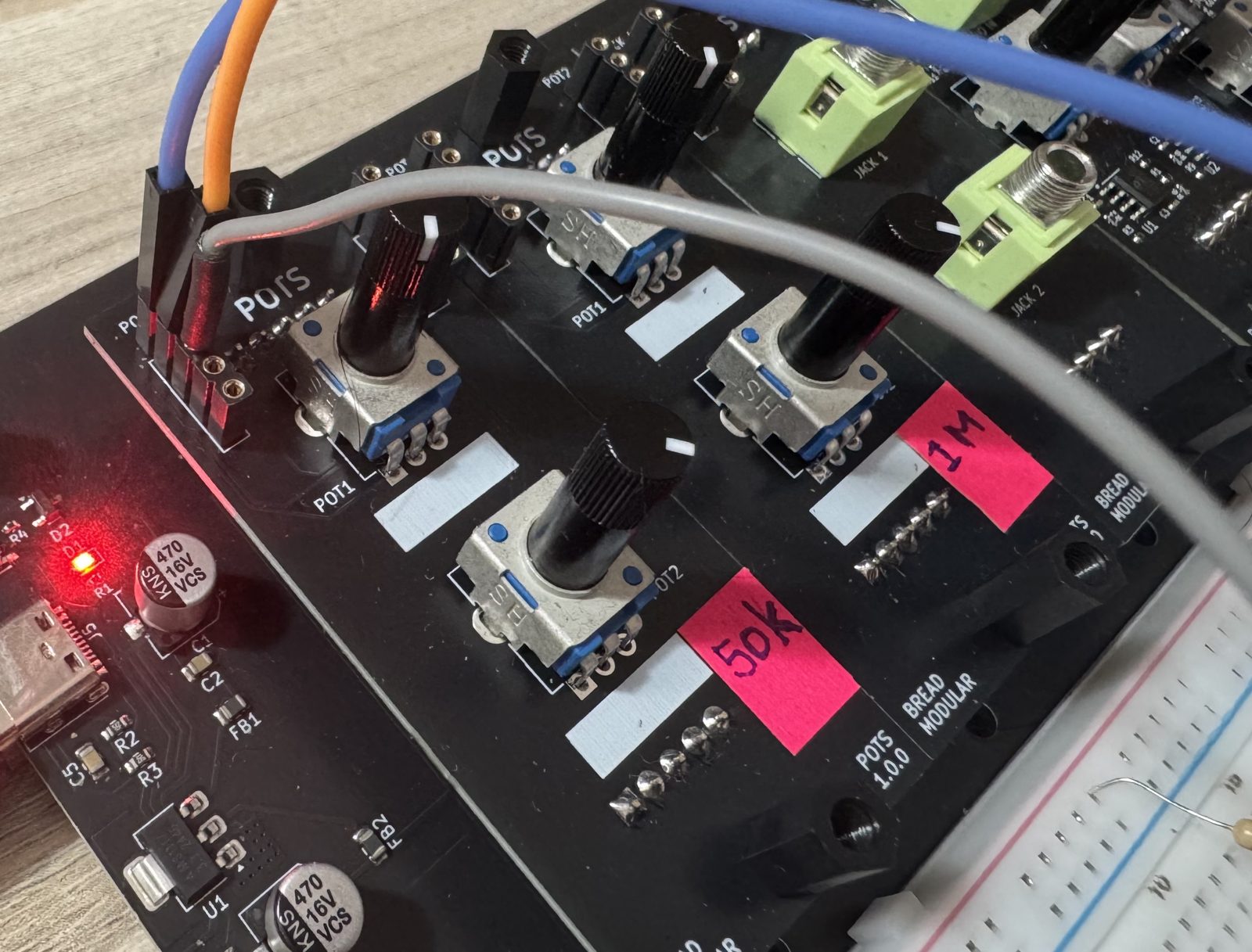
blue - the 16bit A1 output
orange - oscilloscope probe
gray - ground (0V)
As you can see, the midpoint of the waveform changes as we turn the knob. For the line out, this is not a problem as it corrects it. But in some other cases, this could be a problem.
To fix it, instead of connecting the gray wire (ground pin) to 0V, connect it to the midpoint (Vout) of a 1k voltage divider. In this case, our ground will be 1.65V.
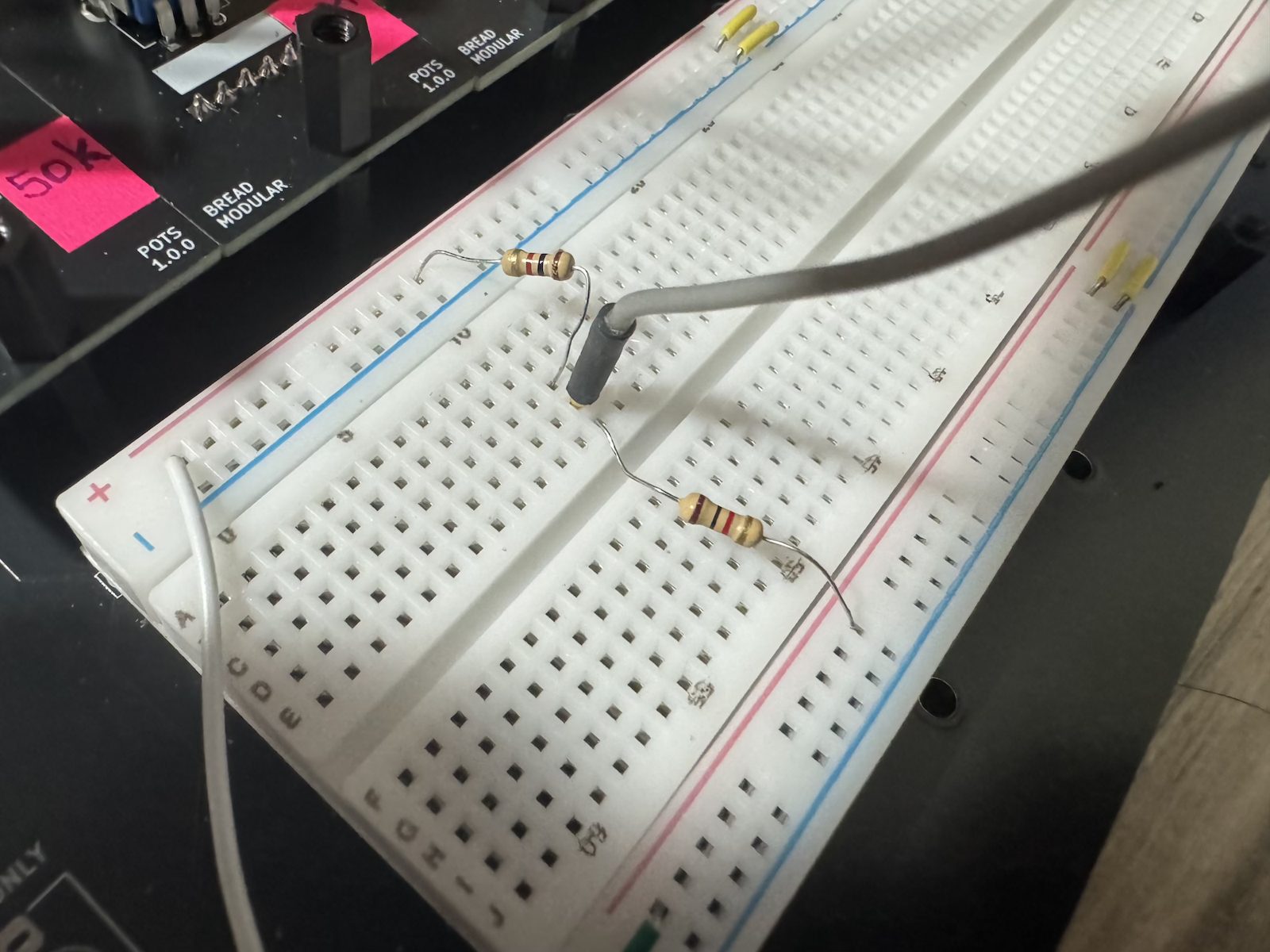
🚨 As you can see, the midpoint still changes. That's mainly because our oscilloscope probe is not ideal. We are going to fix that in the next lesson.