
Lesson 4 of 6
Lighting Up an LED
Learn about LED polarity, limit current with a resistor and drive an LED with a pulse.
In the rest of this course, we are going to build a Vactrol-based VCA using what we learned about opamps. We will use a Vactrol as a resistor that can be controlled with a voltage (from an LFO or envelope generator). But first, we need to learn about LEDs.
Now we are going to drive (light up) an LED. Unlike resistors, LEDs have polarity, which means they have + and - pins. Current needs to flow from one end to the other. See below:
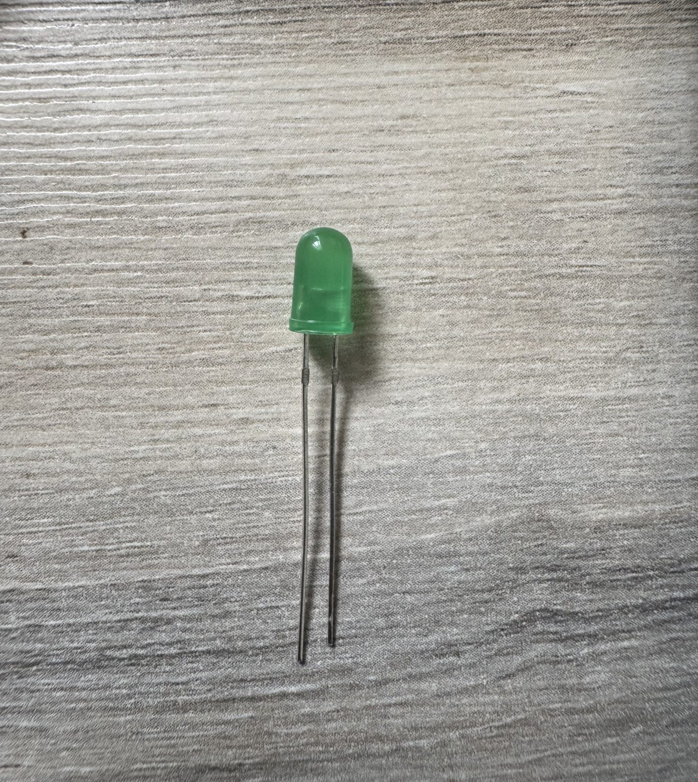
You need to provide a minimum voltage across these pins. For a green LED, it's about 2V, but it can go as low as 1.8V.
🚨 You cannot connect an LED directly to a voltage source (assuming it's higher than 2V).
If you connect it directly, the LED tries to draw as much current as it can from the power source and eventually it will blow up (maybe this is a good experiment for you to try). That's because an LED can only take up to around 10mA of current, while our Bread Modular setup can supply up to 150mA.
Wiring Up an LED
So, we need to limit the current with a resistor as shown below:
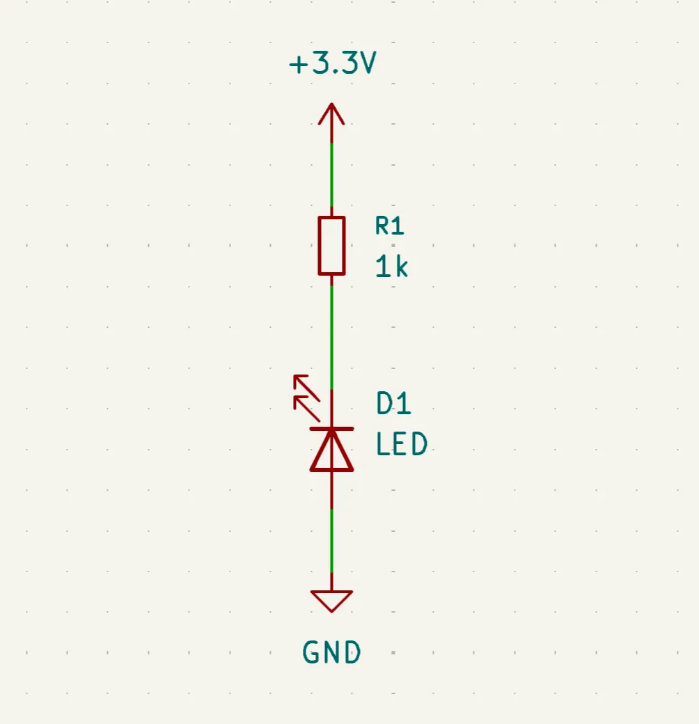
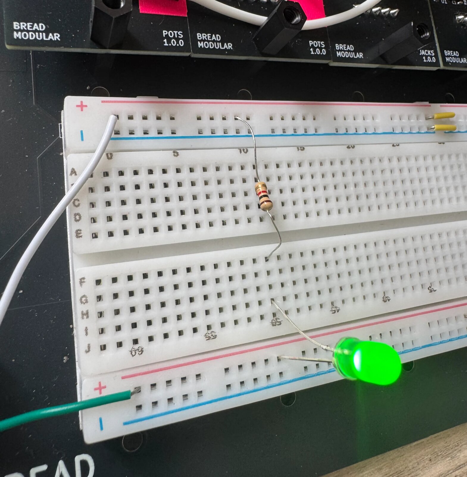
As you can see, the 1k resistor limits the current. If you measure it, it restricts the current to about 1 milliamp (1mA). That's more than enough for an LED to light up.
🛠 Try replacing the 1k resistor with other values and see whether the LED brightness changes.
💡 Measuring current is out of scope for this course, but it's very simple. Check out this ChatGPT thread for that.
Sending a Pulse Instead of 3.3V
Have a look at the following:
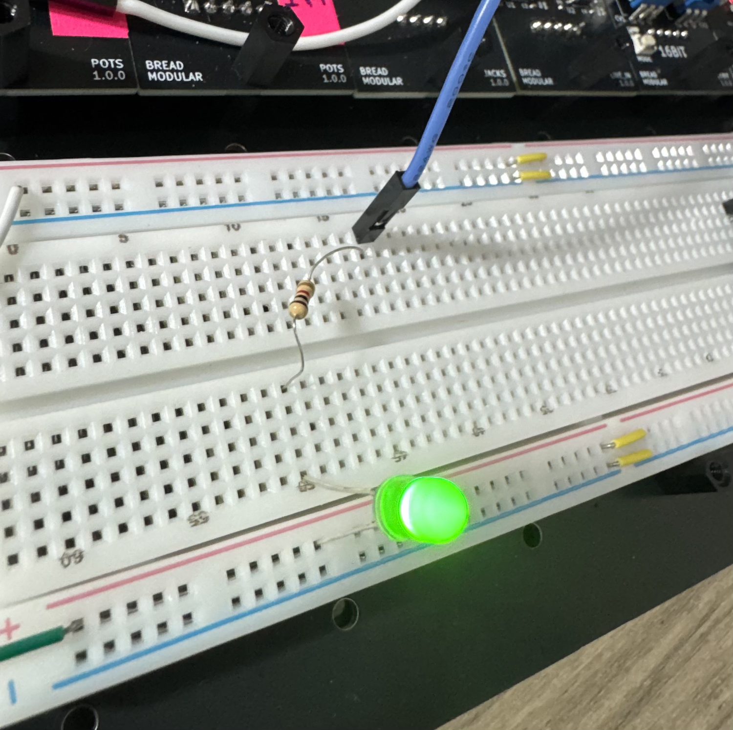
Here, the blue wire is connected to the 16bit's G1 output. It carries the pulse output, whose frequency is controlled via the 2nd potentiometer of the 16bit.